In safety-critical systems engineering, poorly defined requirements represent a significant vector for systematic failures. Unlike random hardware failures, which can be statistically modeled and mitigated via component redundancy, systematic errors are baked directly into the system architecture through vague definitions, incomplete environmental assumptions, or fractured traceability matrices.
Navigating functional safety compliance under master standards like IEC 61508 or ISO 26262 requires a structured approach to requirements engineering. This guide outlines the lifecycle bifurcation of safety requirements, the technical realities of integrating commercial off-the-shelf (COTS) hardware, and the implementation of robust traceability frameworks.
Requirements Bifurcation: High-Level vs. Low-Level Lifecycles
A foundational misstep in complex automation projects is treating all requirements as part of a single, static development stream. Compliant system safety engineering requires a sharp distinction between the high-level system safety requirements lifecycle and the low-level technical design requirements lifecycle.
High-Level System Safety Requirements
These requirements define the core risk-mitigation parameters of the system and must be completely locked down during the early conceptual and architectural phases. Derived directly from the Preliminary Hazard Analysis (PHA) and Hazard Analysis and Risk Assessment (HARA), high-level requirements establish what safety functions the system must perform and the target Safety Integrity Level (SIL) or Performance Level (PL) each function must achieve. Attempting to modify high-level safety goals mid-lifecycle disrupts the entire safety case and invalidates downstream architectural choices.
Low-Level Technical Requirements
Conversely, low-level requirements are developed dynamically and iteratively in parallel with the actual physical and software design. These requirements detail how the high-level safety goals are physically executed within the control system architecture. They specify exact voltage thresholds, sensor response times, communication protocols, and register maps. Because engineering design is an evolutionary process, low-level requirements must remain flexible enough to adapt to hardware revisions, layout adjustments, and interface optimization without shifting the overarching safety goals.
The Realities of Safety-Rated COTS Integration
To accelerate development timelines and manage commercial pressures, engineering teams frequently rely on safety-rated Commercial Off-The-Shelf (COTS) equipment, such as pre-certified safety PLCs, laser scanners, or safe servo drives. While the use of pre-certified hardware is highly beneficial, a common misconception is that sourcing a certified component inherently makes the broader system compliant.
The true engineering challenge in functional safety does not lie in sourcing hardware; it resides in the verification of the complex integration and interface safety cases.
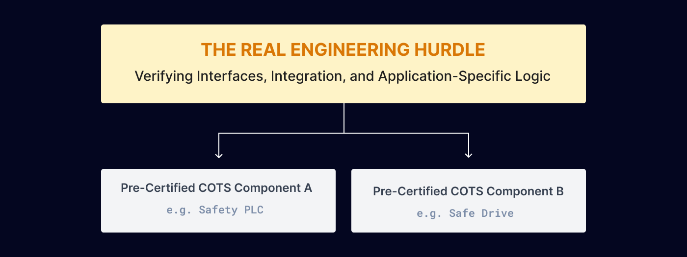
When integrating multiple COTS components, safety engineers must meticulously validate the interfaces across subsystem boundaries. Key integration focus areas include:
Safety Function Mapping: Ensuring that the safety manual assumptions provided by the COTS manufacturer perfectly match the actual environmental and operational conditions of the final application.
Diagnostic Coverage Alignment: Verifying that cross-subsystem communication protocols (such as PROFIsafe or CIP Safety) do not introduce latency or data corruption that exceeds the predefined safe state response time.
Common-Cause Vulnerabilities: Analyzing whether the integration of independent COTS components introduces hidden single points of failure, such as shared power distribution buses or non-redundant network infrastructure.
Implementing Bidirectional Traceability Across the V-Model
To successfully pass a strict third-party compliance audit, an engineering team must provide objective evidence that every safety requirement was not only implemented but also rigorously verified. This requires the establishment of bidirectional traceability across the entire V-model lifecycle.
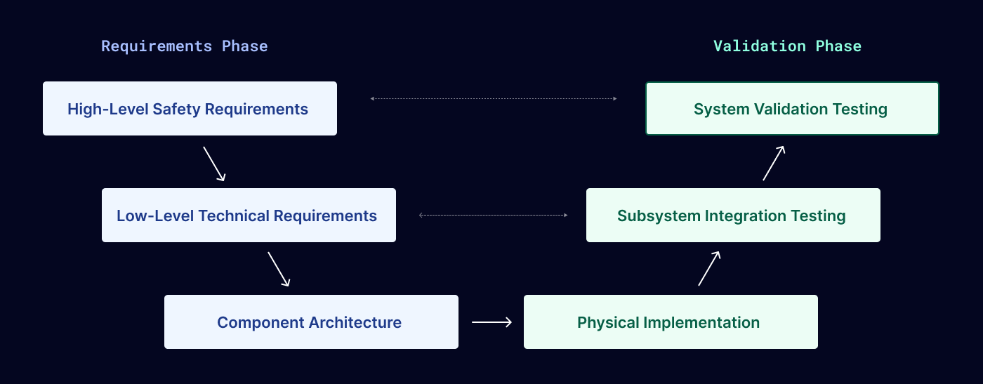
Bidirectional traceability means that an engineer can trace a safety requirement in two distinct directions:
Forward Traceability: Mapping a high-level system safety requirement down through low-level hardware design specifications, into physical implementation, and forward to the exact test case that validates its performance.
Backward Traceability: Verifying that every test case, line of system validation, and physical component can be traced directly back to an authorized, documented safety requirement. This ensures that no "orphaned" features or undocumented behaviors are introduced into the control architecture.
This verification loop is maintained via a Requirements Traceability Matrix (RTM). The RTM acts as a living compliance ledger, proving to external auditors that the system contains no unverified safety assumptions and that the final validation phase perfectly matches the original design intent.
Engineering Management Checklist for Traceability
Requirement Freezing: Ensure high-level system safety goals are locked down and signed off before detailing low-level technical execution paths.
COTS Assumption Review: Audit the manufacturer-provided safety manuals for all COTS hardware to verify that interface constraints match your specific application boundaries.
RTM Validation: Verify that the Requirements Traceability Matrix demonstrates a clear, continuous link from initial conceptual hazards down to final test reports before initiating compliance audits.